


CSP Patents
A parabolic solar concentrator
Published: 27 December 2002
Patent No: WO 2002103256
Author/s: Mauro Giuseppe Gianuzzi, Adio Meliozzi, Ettore Diego Prischich, Carlo Rubbia, Mauro Vignoli
Applicant: ENEA
Patent No: WO 2002103256
Author/s: Mauro Giuseppe Gianuzzi, Adio Meliozzi, Ettore Diego Prischich, Carlo Rubbia, Mauro Vignoli
Applicant: ENEA
DESCRIPTION (OCR text may contain errors)
PARABOLIC SOLAR CONCENTRATOR.
•k -k Jc -k -k
The present invention relates to the sector of the solar plants for the production of energy and particularly to' a panel or module of cilindric parabolic collectors, with a honeycomb structure, apt to support thin mirrors, which concentrate the rays of sunlight on a tube, within which a fluid to be headed flows .
The present systems for concentration of the rays of sunlight are generally formed of curved glass mirrors having a 4mm thickness and cylindric-parabolic shape, with the 166cm spaced focus and a 576cm parabole span, which are supported by a reticular tube structure, which has a strength necessary for withstanding the deformation forces due to the wind action. The mirror is a self-supporting one and is secured to the understanding structure by means of supports glued thereto.
Even if this rectangular structure is sufficiently rigid and strong, it has, however, the drawback of being very heavy and requires very difficult assembling and alignment operations of the mirrors. Another drawback of the above said prior art consists in that said rigid mirrors, mounted on the reticular structure, need to be checked as to the convergence of the sunlight rays on the receiving tube, within which a fluid to be heated flows, an operation which causes high installation costs.
Said reflecting surfaces of the present plants are stable for a long time, from both the optical and mechanical points of view and can be easily cleaned, but in particular working conditions they result to be fragile. In fact, in some cases the rupture stresses have -been exceeded owing to the forces and vibrations caused by the wind and by the interactions with the support structures.
For these reasons the glass panels, arranged at the most exposed extremities of said structures, have been strengthened by glass fibers, for improving their mechanical characteristics. The present cost of the curved mirrors varies between 52 and 60 $/m2 , but in any case it should be considered as an additional cost for the assemblage and alignment of the mirrors in situ, which may be estimated in 60 $/m2. The mirrors should have excellent optical proprieties and need support structures for allowing the movement of the sun; all this being extremely expensive and requiring an alternative system for reducing the costs of the collectors.
The main object of the present invention is that to overcome the above said problems and drawbacks by a module or panel having a parabolic shape with a honeycomb structure for supporting • thin glass mirrors, apt to concentrate the rays of sunlight on a tube, in which a fluid flows, which is headed by the solar energy at a temperature suitable to be used for the production of the solar energy. Preferably, the module is supported by a tubular element extending longitudinally, so as to support the panel honeycomb structure by means of suitable transverse fins and/or ribs .
This and other objects of the invention will be better understood from the following disclosure with reference to the enclosed drawings, which show by way of example two preferred embodiments of the present invention. In the drawings : figure 1 schematically shows the structure of a panel according to the invention; figure 2 shows the parabolic transverse profile of the panel ; figure 4 is a perspective view, which schematically represents a first embodiment of the invention, in which the panels with a honeycomb structure have a variable thickness; figure 4, similar to the previous one, shows a second embodiment of the invention, in which the honeycomb panels have a constant thickness; figure 5 represents an example of a rib supporting the honeycomb panels; figure 6 shows a plant portion with a plurality of panels aligned to form a solar concentrator; and figure 7 shows a perspective view of a honeycomb panel having a constant thickness, in which the support tibs are formed by variable section fins.
As known, the reflecting panels and their support structures play an important role for determining the overall efficiency of solar power plants: these equipments should convey the great quantity of energy inciding on a receiving tube.
For obtaining this aim, the entire support structure should have a low deformation levels caused by the winds in the working conditions: in fact, in certain conditions said mirrors behave as sails.
The parabolic shape of the panels has a wide surface which could cause distortions due to the flexure and torsion of the entire structure. In any case, for avoiding excessive reductions of the optical efficiency, the deformation due to flexion and torsion moments should be smaller than ± 0,15° (with respect to the normal of the reflecting surface) , whereas the induced tensions should not exceed the maximum tensile stresses of the material, particularly of the mirrors. 0,15 degrees corresponds to the value of the maximum deviation of the reflected sun's ray, with respect to an ideal situation, in which there is no deformation of the parable. In any case, the mirrors should be easily replaceable and adjustable in situ. Referring to the above listed figures, for overcoming the problems characterising the known technique, the present invention provides the use of composite materials having a high stiffness and a low weight, such as honeycomb structures 1, on which there should be supported the thin, mirrors 2 having a thickness of about 1,1mm or a slightly greater one .
Such a construction kind may be performed at low costs and with reflecting glass panels 2 having a small thickness, which are cold deformed. The intrinsic rigidity of the (sandwich) panels allows to use panels having a greater size with respect to the sizes of the mirrors as at present employed. Further economical advantages are potentially possible by reducing materials and necessary support structures. The sandwich panels P consist of a central layer or core 1 with a honeycomb structure, preferably of aluminium, on which two very thin layers (skins) 3, preferably of steel, are fastened, which improve the sturdiness properties and the shape of the entire panel . The high flexure strengths are assured by two outer skins 3, which are subjected to tensive stresses. The central layer or core 1, formed by small honeycomb cells, should also have a high compression resistance for keeping constant the distance between the skins.
The thermal expansion coefficients of the outer layers (skins) 3 are similar to those of the' glass 1, for avoiding raptures caused by differential elongations of the two materials. As it will be disclosed hereafter, steel resulted to be the most suitable material for this aim, whereas aluminium, owing to its low weight, resulted to be the most suitable material for the core 1.
The thin glass (mirror) 2 is fastened to the skin 3 of the concave surfaces of the panel P.
The novel curved honeycomb structure according to the invention (figures 2 to 4 and 7) , having reflecting surfaces 2 at the upper concave portion, improves the sturdiness by avoiding dangerous deformations, which would hinder the use of thin and light mirrors (less resistant) . This constructive solution, beside to offer conveniently a high sturdiness-weight ratio, reduces also the material and production costs.
The intrinsic sturdiness of the honeycomb structure facilitates the use of panels P having greater sizes, thus causing a further reduction of installation and regulation costs of the mirrors in situ, which in the present existing plants corresponds to the cost of a panel.
Moreover, the complexity of the present support structures is strongly reduced thanks to that these panels P, even if light, are self-supporting.
In the embodiment of Fig. 3, there are shown a panel with honeycomb structure and a varying thickness, which decreases starting from of the parable apex towards the longitudinal parable edges.
The above disclosed cylindrical support tube 4 has the function of transmitting to the entire structure the twisting moment of the motor MT, particularly to the reflecting parabolic panels. For simplifying the production process, the tube 4 could be constructed by folding a flat sheet according to a closed polygonal shape, near to a circle, which is welded at its extremities.
In alternative to this configuration, according to the invention a second embodiment is provided (see Fig. 4), comprising curved honeycomb panels with a constant thickness, which are secured to the longitudinal support tube 4 by suitable support fins 5 integral therewith.
Preferably, each panel P has a length of about 3 meters and the aluminium honeycomb layer has a thickness of 25mm and is lined by 0,5mm thick skins of carbon steel.
These carbon steel skins are treated by an economic electro-galvanization process of their surfaces for protecting the material from corrosion and increasing the adhesion force of the mirrors. To said mirrors, by means of an adhesive layer, a waterproof material is applied for avoiding an electro-chemical corrosion which could take place by contact of the silver-plated surfaces with water
(an electrolyte) . This is one of the main reasons of corrosion of the silver plated on the glass.
The thin mirror 2 is fastened to the panel by glueing with a epoxidic or acrylic glue and applying by means of a curved spindle a pressure on the concave support surface. The use of two steel sheets or skins 3 is important for assuring both the thermal stability and integrity of the mirror and maintaining a good optical characteristic in a wide temperature range. In fact, the thermal expansion coefficient of the steel (10 , 8÷12 , 6x10 6 m/m°C) is near to that of the glass (5 , 6÷12 , 6x10 s m/m°C) , whereas those of the aluminium (21,6x10 6 m/m°C) and of the plastic (50x10 6 m/m°C) are much higher with respect to the glass.
The difference between the expansion coefficients of the glass and steel minimize the stresses caused by temperature changes and optical distortion, whereas the arrangement of the steel skins (and thus of the same material) on both the faces of the honeycomb layer, advantageously minimizes the curvature change. The modulus of elasticity of the steel (207.000 Mpa), higher than that of the glass (69.000Mpa) assures the maintenance of the initial curvature of the sandwich element, even if the room temperature changes .
Instead of the steel skins 3 , it could be employed skins of a lighter material, such as aluminium, but in such a case it would be advisable to insert a glass fibre layer between the aluminium skin and thin reflecting glass 2, all this for obtaining the different thermal expansions of the materials .
The honeycomb panels P should be supported by a sufficiently rigid structure for avoiding deformation, which could cause a reduction of the optical efficiency of the entire structure. According to a peculiar feature of the invention, an integration between the honeycomb panels and the support structure is provided: this solution simplifies the structure and facilitates its installation, attaining thus an improvement with respect to the conventional solution (thick glass mirrors - rectangular metal structure with hollow tubes) .
A simple comparison of costs (per surface unit) between the conventional thick glass mirrors and the above disclosed thin mirrors 2 supported by honeycomb panels P does not allow to wholly emphasize the advantages of the invention, but when considering the cost reductions for the installed collector, whereby the structure and its installation weight in almost equal proportions (receiving tube and motorization included) , the advantages are evident .
As it has been already mentioned, the structure supporting- each module P, to which the reflecting surfaces 2 are fastened, is formed by a cylinder tube 4, which preferably is provided with reinforcement fins or ribs, which connect it to the panels 4 themselves (see Figs. 4, 5 and 7) .
The entire support structure, schematically shown in Fig. 6, consists of a series of modules P of the above said kind. In this example, the modules have a length of 12 meters and a width of about 5,76m. Consequently, with 8, 4 or 2 modules it is possible to have linear parabolic panels with a length of 100, 50 or 25 meters, actuated by a motor MT arranged at the half length, which allows the rotation of the parabolic element for following the displacement of the sun during the day.
The criterion on which the limitation of the entire length of the parabolic element is based, is originated from the need to limit the deformations of the receiving tube caused by the thermal expansions, as well as the torsional deformations caused by the wind action, without utilizing excessively heavy and complete support structures .
The supports at the ends of each module are not secured for allowing the thermal expansions. For minimizing the moment to be supplied by the motor for rotating the panel structure, the rotation axle extends through the centre of gravity of the entire panel. It should be noted that said motor supplies the torque which should overcome the friction forces and possible resistance couple due to the wind. The rotation moment is transmitted from the support tube (hollow) 4 supporting the reflecting structure by means of the above said connection fins 5. The pitch or mutual distance of the fins 5 depends on the geometrical characteristics of the sandwich structure used for supporting the mirrors. In the case of panel with honeycomb core 1 of 2,5cm, the pitch between the fins can reach 3 meters .
For avoiding that the support tube 4 can be subj ected to settlement or collapses in correspondence to the support fins, it is provided to insert flanges or structural reinforcement elements, apt to increase the stiffness of the tube itself, which allows the mechanical connection with the fins 5.
The follower system includes a particular solar sensor and is provided with a feedback signal, which assures an exact alignment and concentration of the sun rays onto the receiving tube 6 with a precision of about 0,1°. The follower operation is monitored by a local computer assisted by a hardware unit assigned to this purpose. In the control room there are provided indicators of the working condition, alarms and diagnostics. Obviously, the control range of the alignment of the collector and possible corrections thereof are of particular importance.
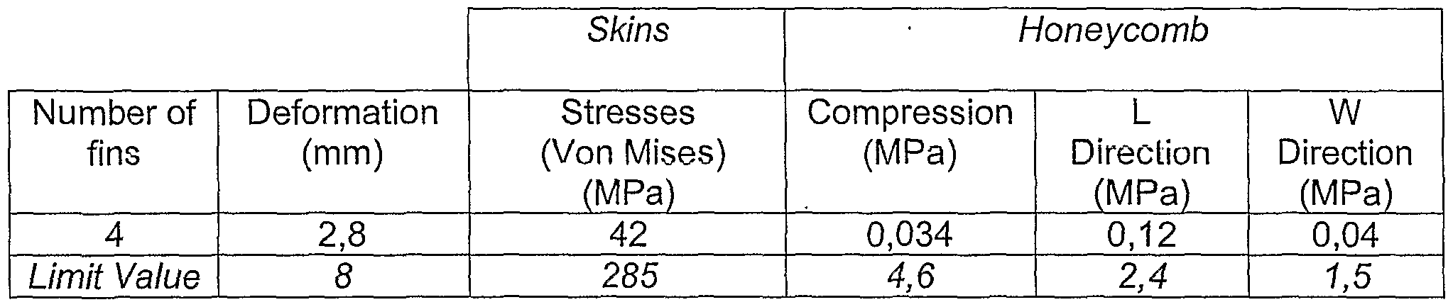
The entire structure is preferably designed to operate in normal conditions at wind speeds between 40 and 60 Km/h and at the limit wind condition of 110 Km/h. At the limit velocity of 110 Km/h, the collector will be turned over and arranged to offer a minimum resistance to the wind, forming an angle of 30° with respect to the horizontal position. For estimating the forces exerted by the wind on the glass panels it has been used the simulation by the FLUENT codex, whereas for estimating the stresses and deformations acting on the materials it has been used the CASTE codex. The FLUENT allows to characterize the pressure profile on the reflecting surface, there being examined also the instability phenomenon caused by the vortexes downstream the reflecting surface, as well as the low frequency oscillations, which cause the vibrations on the mirror surfaces. There have been also performed controls at different inclination angles of the surface with respect to both the reflecting element and support structure. The first preliminary test has been performed on a parabolic honeycomb panel, on which a uniform pressure of 500 N/m2 (80 Km/h) has been exerted. In the specific case, the panel was formed by a core of 2,5cm and two skins of 0,5mm on the outer surfaces, with the features 'resulting from the following table
The test has been carried out by supposing that:
The panel of 12 meters has the same characteristics along its extension: this means that all single panels are connected one with another and form a single module;
The supports (fins on the lower surface) have a high stiffness; The panels have single honeycomb cells and shell shaped elements in the lower and upper wall of the surface layers (skins) ;
The surface layers (skins) are formed of an isotrope material and the honeycomb is formed by a non- homogeneous material . It is of interest to note that although from the numerical simulation (performed by supposing respectively 2, 3 and 4 support fins) there resulted in any case stresses lower than the acceptable maximum values, for having allowable deformations it is necessary to use panels with at least 3 fins: the use of four fins seems to be the most suitable choice. However, the number of fins depends on their structural characteristics and on materials used for attaining the necessary stiffness
The present invention has been disclosed and shown in some preferred embodiments thereof, but it is obvious that a skilled in the art could perform some modifications and technically and/or functionally equivalent replacement without going out from the scope of the present invention.
CLAIMS (OCR text may contain errors)
CLAIMS A module of solar concentrator with bidimensional parabolic profile geometry, characterized by that it comprises one or more self-supporting stiff panels (P) having a parabolic cross section and rectilinear longitudinal extension, which are apt to support thin reflecting surfaces (2) conjugated thereto, said panels being moved by automated motion means for following the movement of the sun during the day; the geometry of said reflecting surfaces (2) being such as to concentrate the incident sun' s rays along a longitudinal axis corresponding to the symmetry axis of a receiving tube (6) , within which a fluid to be heated is flowing. A module according to the preceding claim,
' characterized in that said panels (P) have a sandwich structure having a honeycomb central core (1) and two thin outer skins (3) of a high resistance material, and particularly stiff panels. A module according to the preceding claim, characterized in that the skins (3) have a thermal expansion coefficient similar to that of the thermal surface (2) , thus for avoiding or drastically reducing the deformations which could cause a reduction of the optical efficiency. A module according to any one of the preceding claims, characterized in that the panels (P) are constrained, at their convex face, on longitudinal tubular support element (4) , which is provided with means for rotating it around its axis, so as to move the reflecting surfaces (2) for following the motion of the sun. . A module according to the preceding claim, characterized in that each parabolic panel (P) has a honeycomb structure having a variable thickness, which decreases starting from the parable apex towards the parable longitudinal edges, the panel being fastened to the longitudinal support tube (4) at the central zone having a greater thickness. 6. A module according to claim 4, characterized in that each parabolic panel (P) has a honeycomb structure with a constant thickness and is constrained to the longitudinal support tube (4) by means of transverse support fins (5) . 7. A module according to any one of the preceding claims, characterized in that the panels (P) are about 3 meters long, the panel honeycomb core (2) consists of aluminium, has a thickness of 25mm and is lined by 0,5 mm thick steel skins (3) . 8. A module according to any one of the preceding claims, characterized in that the mirrors (2) are fastened on the concave surface of the panel (P) by an epoxidic or acrylic glue and pressed by means of a curved spindel (M) , the diaphragms or skins of steel assuring both the thermal stability and integrity of the mirror so as to maintain a good optical characteristic within a wide temperature range .
9. A module according to any one of the preceding claims, characterized in that instead of the steel skins (3) there are provided aluminium skins and a further layer of glass fibres is inserted between the concave side of the skin (1) and thin reflecting mirror (2) , such an arrangement obviating the great differences existing between the thermal expansion coefficient of the mirror (2) and that of the aluminium skin (3) . A module according to any one of the preceding claims, characterized in that it is installed in series for a total length till to 100 meters so that all the aligned parabolic panels (P) are rotated by a single motor (MT) placed at the half length of the support tube (4) . A solar plant for the production of energy, characterized in that it comprises a plurality of panels according to the previous claims.
A MODULE OF PARABOLIC SOLAR CONCENTRATOR.
Solar concentrated module with a , bidimensional parabolic profile geometry, comprising one or more rigid self-supporting panels (P) having parabolic cross section and a rectilinear longitudinal extension, said panels being comprised of a central sandwich structure including a central honeycomb core (1) and two thin outer skins (3) of a high resistance material, for attaining thus light and particularly rigid panels.
Said panels (P) are apt to support thin reflecting surfaces (2) connected therewith, the geometry of which being such as to concentrate the incident sunlight rays along a longitudinal receiving tube (6) , within which a fluid to be headed flows. Automated motion means are provided for moving the panels so as to follow the movement of the sun during the day.
Links:
- View PDF
- Link to WIPO